Euler angles

In physics, mathematics, and engineering, Euler angles are three rotation angles, often denoted by 0 ≤ α ≤ 2π, 0 ≤ β ≤ π, and 0 ≤ γ ≤ 2π, although the notation φ, θ, ψ is also common. Any rotation of a 3-dimensional object can be performed by three consecutive rotations over the three Euler angles.
Different conventions are in use: a rotation can be active (the object is rotated, the system of axes is fixed in space), or passive (the object is fixed in space, the axes are rotated).
Also the choice of rotation axes may vary; an active convention common in quantum mechanical applications is the z-y′-z′ convention. Attach a system of Cartesian coordinate axes to the body that is to be rotated (the coordinate frame is fixed to the body and is rotated simultaneously with it); in the figure the body-fixed frame is shown in red and labeled by lowercase letters. First rotate around z, then around the new body-fixed y-axis, y′, and finally around z′. Another convention often used is the z-x′-z′ convention, where instead of over the new y-axis the second rotation is over the new x-axis. Also the z-y-x convention is used (and will be discussed below).
The right-hand screw rule is practically always followed: the rotation axis is a directed line and a positive rotation is as a cork screw driven into the positive direction of the axis. In older literature left-handed Cartesian coordinate frames appear sometimes, but in modern literature right-handed frames are used exclusively.
Euler angles are used in many different branches of physics and engineering. The present article is written from the point of view of molecular physics, where the objects to be rotated are molecules and applications are often of quantum mechanical nature.
The angles are named after the 18th century mathematician Leonhard Euler who introduced in 1765 two of the three for an axially symmetric body where the third angle, γ, does not play a role.[1]
Contents |
[edit] Geometric discussion
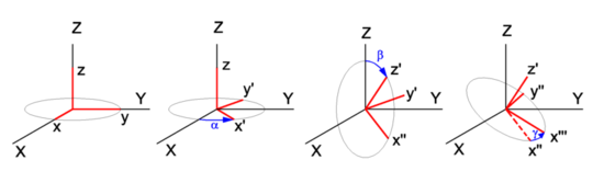
In Figure 1 the space-fixed (laboratory) axes are labeled by capital X, Y, and Z and are shown in black. The body to be rotated is not shown, but a system of axes fixed to it is shown in red. One may use any convenient orthonormal frame as a body-fixed frame. Often the body-fixed axes are principal axes, that means that they are eigenvectors of the inertia tensor of the body. Also symmetry axes, when present, may be used. When the body has symmetry axes, the principal axes often coincide with these.
The z-y′-z′ convention will be followed. Initially, the two frames coincide, and the path to a final arbitrary orientation of the body—and its frame—is depicted on Figure 1. The first rotation is around the z-axis, which coincides with the Z-axis. The x- and y-axis move in a plane perpendicular to the z-axis over an angle α. The second rotation is in a plane through the origin perpendicular to the y′-axis. The angle is β. The present convention has the practical advantage that the z′-axis has the usual spherical polar coordinates α ≡ φ (longitude angle) and β ≡ θ (colatitude angle) with respect to the space-fixed frame.[2] The final rotation is in a plane perpendicular to the z′-axis over an angle γ. From geometric considerations it follows that any orientation of the body-fixed frame in space may be obtained.
Write  for the rotation matrix that describes a rotation around the unit vector
  over an angle
  .
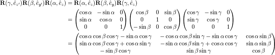
Clearly the three consecutive Euler rotations correspond to rotations around
the unit vectors along the body-fixed axes z, y′, and z′ over angles α β, and γ, respectively. Because a matrix acts on a column vector to its right, the order in the matrix product is as in the leftmost term in the following equation.
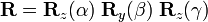
It will be shown that the corresponding matrix product can be written in reverse order (but around fixed, unprimed, axes z, y, z), that is,
.
Clearly the three consecutive Euler rotations correspond to rotations around
the unit vectors along the body-fixed axes z, y′, and z′ over angles α β, and γ, respectively. Because a matrix acts on a column vector to its right, the order in the matrix product is as in the leftmost term in the following equation.
It will be shown that the corresponding matrix product can be written in reverse order (but around fixed, unprimed, axes z, y, z), that is,
Note that the third column contains the Cartesian coordinates with respect to the space-fixed frame of  expressed in sines and cosines of spherical polar angles. The first and second column contain by definition expressions for the Cartesian coordinates of
  and
and  , respectively, but evidently these are not solely in terms of spherical polar angles, γ also enters.
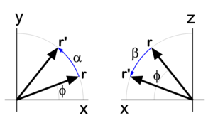
Before proving the first equality in the above equation (reversal of order), we derive the matrix for a rotation around the z-axis, see the left drawing in Figure 2. The rotated vector has components

We used here the relations well-known from trigonometry for the sine and cosine of a sum angle. The derivation of the matrix for a rotation around the y-axis proceeds along the same lines. Note, however, that the angle of a vector with the x-axis decreases by a rotation around the positive y-axis (see right-hand drawing in Figure 2).
To prove the first equality (reversal of the order in the angles), a property of rotation matrices is used. A rotation (orthogonal 3×3) matrix A, transforming a rotation axis, gives rise to the following similarity equation,
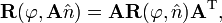
where the superscript T indicates the transpose of the matrix. For rotation matrices the transposed matrix is equal to the inverse of the matrix. From this similarity relation follows that

so that

Also

so that

where it is used that rotations around the same axis commute, that is,

and the required result is proved.
[edit] Algebraic treatment
In the proof that any rotation can be written as three consecutive rotations, an appeal was made to the geometric insight of the reader. The same result can be proved more rigorously by algebraic means. To that end the notation is somewhat shortened:

[edit] Theorem
A proper rotation matrix R can be factorized thus

which is referred to as the Euler z-y-x parametrization, or also as
the Euler z-y-z parametrization.
[edit] Proof
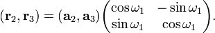
First the Euler z-y-x-parametrization will be proved by an algorithm for the factorization of a given matrix R ≡ (r1, r2, r3). Second the z-y-z parametrization will be proved; this parametrization is—as shown above—equivalent to the z′-y′-z parametrization with angles in reverse order.
- A Fortran subroutine based on the algorithm is given on the code page.
To prove the z-y-x parametrization we consider the matrix product
The columns of the matrix product are for ease of reference designated by a1, a2, and a3. Note that the multiplication by
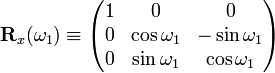
on the right does not affect the first column, so that a1 =
r1 (the first column of R).
Solve  and
and  from the first column of
R (which is known),
from the first column of
R (which is known),
This is possible. First solve for  from
from
Then solve for  from the two equations:
The angles and determine fully the vectors a2 and a3.
Since a1, a2 and a3 are the columns of a
proper rotation matrix they form an orthonormal right-handed system. The plane spanned by a2 and a3 is orthogonal to  and hence the plane contains
  and
and
 . Thus the latter two vectors are a linear combination of the first two,
Since  are
known orthonormal vectors, we can compute
are
known orthonormal vectors, we can compute
These equations give  with
with  .
.
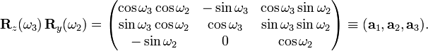
The angle ω1 gives the matrix  with
with

This gives the required z-y-x factorization of the arbitrary proper orthogonal matrix R.
The proof of the Euler z-y-z parametrization is obtained by a small modification of the previous proof. We start by retrieving the spherical polar coordinates and
of the unit vector  , the third column [the rightmost multiplication by Rz(ω1) does not affect r3]. Then consider
or,
 The equation for R can be written as

which proves the Euler z-y-z parametrization. Clearly, this factorization is equal to the one given in the previous section, with

[edit] Note
- ↑ Translation by Ian Bruce of L. Euler, Theoria Motus Corporum Solidorum Seu Rigidorum (Theory of the motion of solid or rigid bodies), Rostock (1765), pdf page 11. Later Euler returned to the angles and gave an alternative derivation, see Translation by Johan Sten of Formulae generales pro translatione quacunque corporum rigidorum (General formulas for the translation of arbitrary rigid bodies), Novi Commentarii academiae scientiarum Petropolitanae, vol. 20, (1776), pp. 189-207
- ↑ In the z-x′-z′ convention the first two Euler angles are not equal to spherical polar angles, in consequence the (m, m′) Wigner D-matrix-element carries the complex phase exp[iπ(m−m′)/2]. This phase is absent in the z-y′-z′ convention