


| 
|
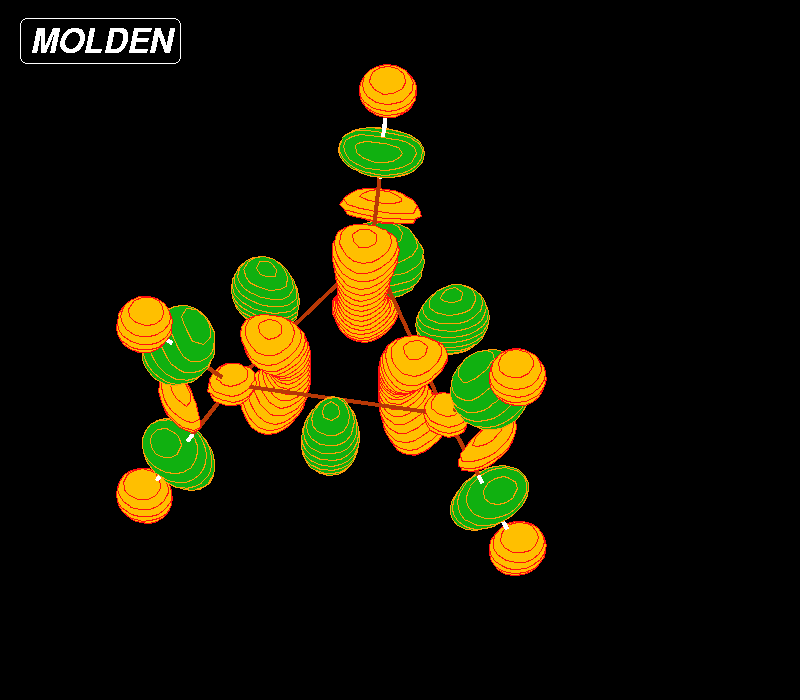
Above left the standard X-windows density/orbital display (molden and gmolden
executable).
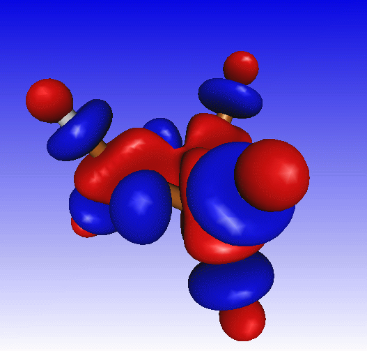
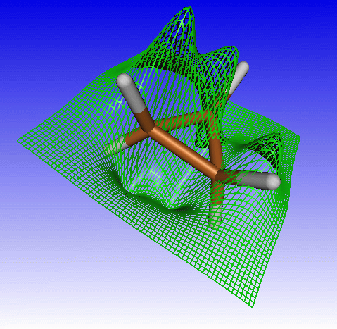
Above right the OpenGL density/orbital display. The latter is only available in
the gmolden executable. You also need to click the Opengl button to switch
from the Xwindow to the OpenGL display: 
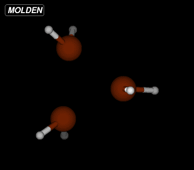
If you have properly set up Molden as as a Chemical MIME type viewer, then click Here to start a molden session with a Gamess output file of an optimize run of cyclopropane. In the molecular display the starting point in the geometry optimization is displayed. The carbon atoms are to far separated for Molden to see them as bonded. After some rotation and selecting Solid and Shade from the Molden Control Window, the display might look something like this:
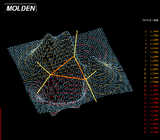
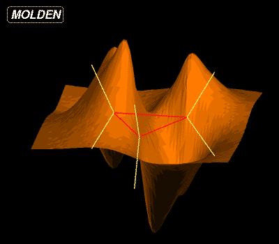
We will not concern ourselves here with viewing the optimization information. Now select Dens. Mode from the Molden Control Window. The main display will now look like this:
| 
|
You will note that Molden now sees the carbon atoms as bonded. This because we are looking at the HOMO (Highest Occupied Molecular Orbital) of the geometry optimised structure. Molden has calculated the MO's function value in a rectangular grid of points. The grid is located in the plane spanned by the three carbons. The colored sticks representing the bonds will be colored orange if both atoms are in the plot plane, otherwise they will be yellow.
 Positioning the cursor over the main window
Press the left mouse button
Drag the mouse while holding down the left mouse button
Release the mouse button when a suiteable rectangle has been selected
Positioning the cursor over the main window
Press the left mouse button
Drag the mouse while holding down the left mouse button
Release the mouse button when a suiteable rectangle has been selected
You can demagnify by clicking the left mouse button in the main window
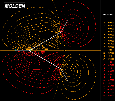
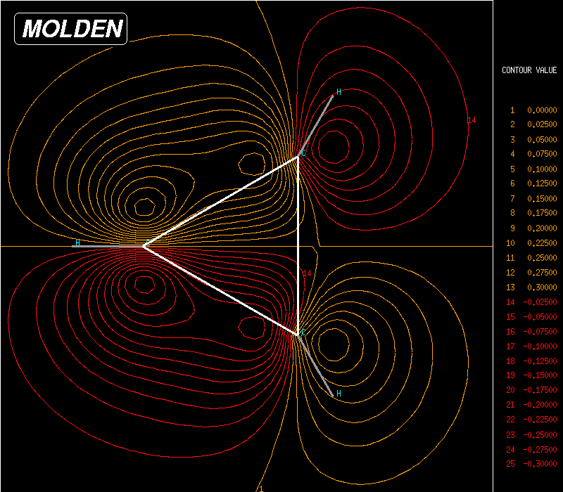
The default plot mode is 3D plus contours. To the right of the display, there will be a table enumerating contour values used in the plot. These contour values correspond with contour lines. Determining which Contour Value corresponds with which Contour Line, can best be accomplished in the euclid plot mode. We can select this mode by selecting Euclid from the Molden Control window ,which by now will look like this:
The main display will look like this:
There is one more plot mode using the planar grid. This is the 3D-X mode, which is very much like the 3D except that is has shading and that it lacks contour lines:
We can select one of the other available orbitals by pressing the Orbital button from the Molden Control Window. Now the Molden Orbital Select window will pop up:
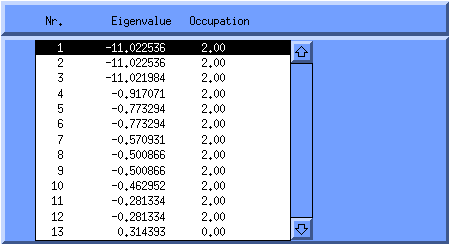
The orbital number is listed together with the MO energies* and the occupation number; the number of electrons in this orbital. You can select a particular orbital by clicking on its corresponding row. You can get rid of the Molden Orbital Select window again by pressing the Orbital button from the Molden Control Window.
(* except when using Mopac/Ampac .gpt files where the MO energies are not avialable)
To be continued.