MPEG-1

MPEG-1 was an early standard for lossy compression of video and audio. It was designed to compress VHS-quality raw digital video and CD audio down to 1.5 Mbit/s (26:1 and 6:1 compression ratios respectively)[1] without obvious quality loss, making Video CDs, digital cable/satellite TV and digital audio broadcasting (DAB) possible.[2] [3]
Today, MPEG-1 has become the most widely compatible lossy audio/video format in the world, and is used in a large number of products and technologies. Perhaps the best-known part of the MPEG-1 standard is the MP3 audio format it introduced.
It should not be assumed that, because of age, MPEG-1 is necessarily obsolete or substantially inferior to newer technologies in all scenarios. In fact the differences between MPEG-1, MPEG-2, and MPEG-4 ASP are actually quite minor. According to Leonardo Chiariglione (co-founder of MPEG): "the idea that compression technology keeps on improving is a myth."[4]
The MPEG-1 standard is published as ISO/IEC-11172.
Contents |
[edit] History
Modeled on the successful collaborative approach and the compression technologies developed by the Joint Photographic Experts Group and CCITT's Experts Group on Telephony (creators of the JPEG image compression standard and the H.261 standard for video conferencing, respectively) the Moving Picture Experts Group (MPEG) working group was established in January 1988. MPEG was formed to address the need for standard video and audio formats, and build on H.261 to get better quality through the use of more complex (non-real time) encoding methods.[2] [5]
Development of the MPEG-1 standard began in May 1988. 14 video and 14 audio codec proposals were submitted by individual companies and institutions for evaluation. The codecs were extensively tested for computational complexity and subjective (human perceived) quality, at data rates of 1.5 Mbit/s. This specific bitrate was chosen for transmission over T-1/E-1 lines and as the approximate data rate of audio CDs.[4] The codecs that excelled in this testing were utilized as the basis for the standard and refined further, with additional features and other improvements being incorporated in the process.[6]
After 20 meetings of the full group in various cities around the world, and 4½ years of development and testing, the final standard (for parts 1-3) was approved in early November 1992 and published a few months later.[7] The reported completion date of the MPEG-1 standard, varies greatly... A largely complete draft standard was produced in September 1990, and from that point on, only minor changes were introduced.[2] In July 1990, before the first draft of the MPEG-1 standard had even been written, work began on a second standard, MPEG-2,[8] intended to extend MPEG-1 technology to provide full broadcast-quality video (as per CCIR-601) at high bitrates (3 - 15 Mbit/s), and support for interlaced video.[9] Due in part to the similarity between the two codecs, the MPEG-2 standard includes full backwards compatibility with MPEG-1 video, so any MPEG-2 decoder can play MPEG-1 videos.[10]
Notably, the MPEG-1 standard very strictly defines the bitstream, and decoder function, but does not define how MPEG-1 encoding is to be performed (although a reference implementation is provided in ISO/IEC-11172-5).[1] This means that MPEG-1 coding efficiency can drastically vary depending on the encoder used, and generally means that newer encoders perform significantly better than their predecessors.[11]
[edit] Applications
- Most popular computer software for video playback includes MPEG-1 decoding, in addition to any other supported formats.
- MPEG-1 video and Layer I/II audio can be implemented without payment of license fees.[12] [13] [14] Due to its age, many of the patents on the technology have expired.
- The popularity of MP3 audio has established a massive installed base of hardware that can playback MPEG-1 Audio.
- "Virtually all digital audio devices" can playback MPEG-1 Audio.[15] Many millions have been sold to-date.
- Before MPEG-2 became widespread, many digital satellite/cable TV services used MPEG-1 exclusively.[11] [5]
- The widespread popularity of MPEG-2 with broadcasters means MPEG-1 is playable by most digital cable and satellite set-top boxes, and digital disc and tape players, due to backwards compatibility.
- MPEG-1 is the exclusive video and audio format used on Video CD (VCD), the first consumer digital video format, and still a very popular home video format around the world.
- The Super Video CD standard, based on VCD, uses MPEG-1 Audio exclusively, as well as MPEG-2 video.
- The DVD-Video format uses MPEG-2 video primarily, but MPEG-1 support is explicitly defined in the standard.
- The DVD-Video standard originally required MPEG-1 Layer II audio for PAL countries, but was changed to allow AC-3/Dolby Digital-only discs. MPEG-1 Layer II audio is still allowed on DVDs, although newer extensions to the format, like MPEG Multichannel, are rarely supported.
- Most DVD players also support Video CD and MP3 CD playback, which use MPEG-1.
- The international Digital Video Broadcasting (DVB) standard primarily uses MPEG-1 Layer II audio, and MPEG-2 video.
- The international Digital Audio Broadcasting (DAB) standard uses MPEG-1 Layer II audio exclusively, due to MP2's especially high quality, modest decoder performance requirements, and tolerance of errors.
[edit] Systems
Part 1 of the MPEG-1 standard covers systems, and is defined in ISO/IEC-11172-1.
MPEG-1 Systems specifies the logical layout and methods used to store the encoded audio, video, and other data into a standard bitstream, and to maintain synchronization between the different contents. This file format is specifically designed for storage on media, and transmission over data channels, that are considered relatively reliable. Only limited error protection is defined by the standard, and small errors in the bitstream may cause noticeable defects.
This structure was later named a program stream: "The MPEG-1 Systems design is essentially identical to the MPEG-2 Program Stream structure."[16] This terminology is more popular, precise (differentiates it from a transport stream) and will be used here.
[edit] Elementary Streams
Elementary streams (ES) are the raw bitstreams of MPEG-1 audio and video, output by an encoder. These files can be distributed on their own, such as is the case with MP3 files.
Additionally, elementary streams can be made more robust by packetizing them, i.e. dividing them into independent chunks, and adding a cyclic redundancy check (CRC) checksum to each segment for error detection. This is the Packetized Elementary Stream (PES) structure.
System Clock Reference (SCR) is a timing value stored in a 33-bit header of each ES, at a frequency/precision of 90 kHz, with an extra 9-bit extension that stores additional timing data with a precision of 27 MHz.[17] [18] These are inserted by the encoder, derived from the system time clock (STC). Simultaneously encoded audio and video streams will not have identical SCR values, however, due to buffering, encoding, jitter, and other delay.
[edit] Program Streams
Program Streams (PS) are concerned with combining multiple packetized elementary streams (usually just one audio and video PES) into a single stream, ensuring simultaneous delivery, and maintaining synchronization. The PS structure is known as a multiplex, or a container format.
Presentation time stamps (PTS) exist in PS to correct this disparity between audio and video SCR values (time-base correction). 90 kHz PTS values in the PS header tell the decoder which video SCR values match which audio SCR values.[17] PTS determines when to display a portion of a MPEG program, and is also used by the decoder to determine when data can be discarded from the buffer.[19] Either video or audio will be delayed by the decoder until the corresponding segment of the other arrives and can be decoded.
PTS handling can be problematic. Decoders must accept multiple program streams that have been concatenated (joined sequentially). This causes PTS values in the middle of the video to reset to zero, which then begin incrementing again. Such PTS wraparound disparities can cause timing issues that must be specially handled by the decoder.
Decoding Time Stamps (DTS), additionally, are required because of B-frames. With B-frames in the video stream, adjacent frames have to be encoded and decoded out-of-order (re-ordered frames). DTS is quite similar to PTS, but instead of just handling sequential frames, it contains the proper time-stamps to tell the decoder when to decode and display the next B-frame, ahead of its anchor (P- or I-) frame. Without B-frames in the video, PTS and DTS values are identical.[20]
[edit] Multiplexing
To generate the PS, the multiplexer will interleave the (two or more) packetized elementary streams. This is done so the packets of the simultaneous streams can be transferred over the same channel and are guaranteed to both arrive at the decoder at precisely the same time. This is a case of time-division multiplexing.
Determining how much data from each stream should be in each interleaved segment (the size of the interleave) is complicated, yet an important requirement. Improper interleaving will result in buffer underflows or overflows, as the receiver gets more of one stream than it can store (eg. audio), before it gets enough data to decode the other simultaneous stream (eg. video). The MPEG Video Buffer Verifier (VBV) assists in determining if a multiplexed PS can be decoded by a device with a specified data throughput rate and buffer size.[21] This offers feedback to the muxer and the encoder, so that they can change the mux size or adjust bitrates as needed for compliance.
The PS, additionally, stores aspect ratio information which tells the decoder how much to stretch the height or width of a video when displaying it. Different display devices (such as computer monitors and televisions) have different pixel heights/widths, which will result in video encoded for one appearing "squished" when played on the other, unless the aspect ratio information in the PS is used to compensate.
[edit] Video
Part 2 of the MPEG-1 standard covers video and is defined in ISO/IEC-11172-2.
MPEG-1 Video exploits perceptual compression methods to significantly reduce the data rate required by a video stream. It reduces or completely discards information in certain frequencies and areas of the picture that the human eye has limited ability to fully perceive. It also utilizes effective methods to exploit temporal (over time) and spatial (across a picture) redundancy common in video, to achieve better data compression than would be possible otherwise. (See: Video compression)
[edit] Color Space
Before encoding video to MPEG-1 the color-space is transformed to Y'CbCr (Y'=Luma, Cb=Chroma Blue, Cr=Chroma Red). Luma (brightness, resolution) is stored separately from chroma (color, hue, phase) and even further separated into red and blue components. The chroma is also subsampled to 4:2:0, meaning it is decimated by one half vertically and one half horizontally, to just one quarter the resolution of the video.[1]
Because the human eye is much less sensitive to small changes in color than in brightness, chroma subsampling is a very effective way to reduce the amount of video data that needs to be compressed. On videos with fine detail (high spatial complexity) this can manifest as chroma aliasing artifacts. Compared to other digital compression artifacts, this issue seems to be very rarely a source of annoyance.
Because of subsampling, Y'CbCr video must always be stored using even dimensions (divisible by 2), otherwise chroma mismatch ("ghosts") will occur, and it will appear as if the color is ahead of, or behind the rest of the video, much like a shadow.
Y'CbCr is often inaccurately called YUV which is only used in the domain of analog video signals. Similarly, the terms luminance and chrominance are often used instead of the (more accurate) terms luma and chroma.
[edit] Resolution/Bitrate
MPEG-1 supports resolutions up to 4095×4095 (12-bits), and bitrates up to 100 Mbit/s.[5]
MPEG-1 videos are most commonly seen using Source Input Format (SIF) resolution: 352x240, 352x288, or 320x240. These low resolutions, combined with a bitrate less than 1.5 Mbit/s, make up what is known as a constrained parameters bitstream (CPB), later renamed the "Low Level" (LL) profile in MPEG-2. This is the minimum video specifications any decoder should be able to handle, to be considered MPEG-1 compliant. This was selected to provide a good balance between quality and performance, allowing the use of reasonably inexpensive hardware of the time.[2] [5]
[edit] Frame/Picture/Block Types
MPEG-1 has several frame/picture types that serve different purposes. The most important, yet simplest are I-frames.
[edit] I-Frames
I-frame is an abbreviation for Intra-frame, so-called because they can be decoded independently of any other frames. They may also be known as I-pictures, or keyframes due to their somewhat similar function to the key frames used in animation. I-frames can be considered effectively identical to baseline JPEG images.[5]
High-speed seeking through an MPEG-1 video is only possible to the nearest I-frame. When cutting a video it is not possible to start playback of a segment of video before the first I-frame in the segment (at least not without computationally-intensive re-encoding). For this reason, I-frame-only MPEG videos are used in editing applications.
I-frame only compression is very fast, but produces very large file sizes: a factor of 3× (or more) larger than normally encoded MPEG-1 video, depending on how temporally complex a specific video is.[2] I-frame only MPEG-1 video is very similar to MJPEG video. So much so that very high-speed and theoretically lossless (in reality, there are rounding errors) conversion can be made from one format to the other, provided a couple restrictions (color space and quantization matrix) are followed in the creation of the bitstream.[22]
The length between I-frames is known as the group of pictures (GOP) size. MPEG-1 most commonly uses a GOP size of 15-18. i.e. 1 I-frame for every 14-17 non-I-frames (some combination of P- and B- frames). With more intelligent encoders, GOP size is dynamically chosen, up to some pre-selected maximum limit.[5] This is known as scene change detection.
Limits are placed on the maximum number of frames between I-frames due to decoding complexing, decoder buffer size, recovery time after data errors, seeking ability, and accumulation of IDCT errors in low-precision implementations most common in hardware decoders (See: IEEE 1180-1990).
[edit] P-frames
P-frame is an abbreviation for Predicted-frame. They may also be called forward-predicted frames, or inter-frames (B-frames are also inter-frames).
P-frames exist to improve compression by exploiting the temporal (over time) redundancy in a video. P-frames store only the difference in image from the frame (either an I-frame or P-frame) immediately preceding it (this reference frame is called the anchor frame).
The difference between a P-frame and its anchor frame is calculated using motion vectors on each macroblock of the frame (see below). Such motion vector data will be embedded in the P-frame for use by the decoder.
A P-frame can contain any number of intra-coded blocks, in addition to any forward-predicted blocks.[23]
If a video drastically changes from one frame to the next (such as a scene change), it is more efficient to encode it as an I-frame.
[edit] B-frames
B-frame stands for bidirectional-frame. They may also be known as backwards-predicted frames or B-pictures. B-frames are quite similar to P-frames, except they can make predictions using both the previous and future frames (i.e. two anchor frames).
It is therefore necessary for the player to first decode the next I- or P- anchor frame sequentially after the B-frame, before the B-frame can be decoded and displayed. This makes B-frames very computationally complex, requires larger data buffers, and causes an increased delay on both decoding and during encoding. This also necessitates the display time stamps (DTS) feature in the container/system stream (see above). As such, B-frames have long been subject of much controversy, they are often avoided in videos, and are sometimes not fully supported by hardware decoders.
No other frames are predicted from a B-frame. Because of this, a very low bitrate B-frame can be inserted, where needed, to help control the bitrate. If this was done with a P-frame, future P-frames would be predicted from it and would lower the quality of the entire sequence. However, similarly, the future P-frame must still encode all the changes between it and the previous I- or P- anchor frame (a second time) in addition to much of the changes being coded in the B-frame. B-frames can also be beneficial in videos where the background behind an object is being revealed over several frames, or in fading transitions, such as scene changes.[2] [5]
A B-frame can contain any number of intra-coded blocks and forward-predicted blocks, in addition to backwards-predicted, or bidirectionally predicted blocks.[5] [23]
[edit] D-frames
MPEG-1 has a unique frame type not found in later video standards. D-frames or DC-pictures are independent images (intra-frames) that have been encoded DC-only (AC coefficients are removed—see DCT below) and hence are very low quality. D-frames are never referenced by I-, P- or B- frames. D-frames are only used for fast previews of video, for instance when seeking through a video at high speed.[2]
Given moderately higher-performance decoding equipment, this feature can be approximated by decoding I-frames instead. This provides higher quality previews, and without the need for D-frames taking up space in the stream, yet not improving video quality.
[edit] Macroblocks
MPEG-1 operates on video in a series of 8x8 blocks for quantization. However, because chroma (color) is subsampled by a factor of 4, each pair of (red and blue) chroma blocks corresponds to 4 different luma blocks. This set of 6 blocks, with a resolution of 16x16, is called a macroblock.
A macroblock is the smallest independent unit of MPEG video. Motion vectors (see below) operate solely at the macroblock level.
If the height and/or width of the video is not exact multiples of 16, a full row of macroblocks must still be encoded (though not displayed) to store the remainder of the picture (macroblock padding). This wastes a significant amount of data in the bitstream, and is to be strictly avoided.
Some decoders will also improperly handle videos with partial macroblocks, resulting in visible artifacts.
[edit] Motion Vectors
To decrease the amount of spatial redundancy in a video, only blocks that change are updated, (up to the maximum GOP size). This is known as conditional replenishment. However, this is not very effective by itself. Movement of the objects, and/or the camera may result in large portions of the frame needing to be updated, even though only the position of the previously encoded objects has changed. Through motion estimation the encoder can compensate for this movement and remove a large amount of redundant information.
The encoder compares the current frame with adjacent parts of the video from the anchor frame (previous I- or P- frame) in a diamond pattern, up to a (encoder-specific) predefined radius limit from the area of the current macroblock. If a match is found, only the direction and distance (i.e. the vector of the motion) from the previous video area to the current macroblock need to be encoded into the inter-frame (P- or B- frame). The reverse of this process, performed by the decoder to reconstruct the picture, is called motion compensation.
A predicted macroblock rarely matches the current picture perfectly, however. The differences between the estimated matching area, and the real frame/macroblock is called the prediction error. The larger the error, the more data must be additionally encoded in the frame. For efficient video compression, it is very important that the encoder is capable of effectively and precisely performing motion estimation.
Motion vectors record the distance between two areas on screen based on the number of pixels (called pels). MPEG-1 video uses a motion vector (MV) precision of one half of one pixel, or half-pel. The finer the precision of the MVs, the more accurate the match is likely to be, and the more efficient the compression. There are trade-offs to higher precision, however. Finer MVs result in larger data size, as larger numbers must be stored in the frame for every single MV, increased coding complexity as increasing levels of interpolation on the macroblock are required for both the encoder and decoder, and diminishing returns (minimal gains) with higher precision MVs. Half-pel was chosen as the ideal trade-off. (See: qpel)
Because neighboring macroblocks are likely to have very similar motion vectors, this redundant information can be compressed quite effectively by being stored DPCM-encoded. Only the (smaller) amount of difference between the MVs for each macroblock needs to be stored in the final bitstream.
P-frames have 1 motion vector per macroblock, relative to the previous anchor frame. B-frames, however, can use 2 motion vectors; one from the previous anchor frame, and one from the future anchor frame.[23]
Partial macroblocks, and black borders/bars encoded into the video that do not fall exactly on a macroblock boundary, cause havoc with motion prediction. The block padding/border information prevents the macroblock from closely matching with any other area of the video, and so, significantly larger prediction error information must be encoded for every one of the several dozen partial macroblocks along the screen border. DCT encoding and quantization (see below) also isn't nearly as effective when there is large/sharp picture contrast in a block.
An even more serious problem exists with macroblocks that contain significant, random, edge noise, where the picture transitions to (typically) black. All the above problems also apply to edge noise. In addition, the added randomness is simply impossible to compress significantly. All of these effects will lower the quality (or increase the bitrate) of the video substantially.
[edit] DCT
Each 8x8 block is encoded using the Forward Discrete Cosine Transform (FDCT).[24] This process by itself is theoretically lossless, and is reversed by the Inverse DCT (IDCT) upon playback to produce the original values. In reality, there are some (sometimes large) rounding errors. The minimum allowed accuracy of a DCT implementation is defined by IEEE 1180-1990 (now ISO/IEC 23002-1).
The FDCT process converts the 64 uncompressed pixel values (brightness) into 64 different frequency values. One (large) DC coefficient, which is the average of the entire 8x8 block, and 63 smaller AC coefficients, which are positive or negative values, each relative to the value of the DC coefficient.
An example FDCT encoded 8x8 block:
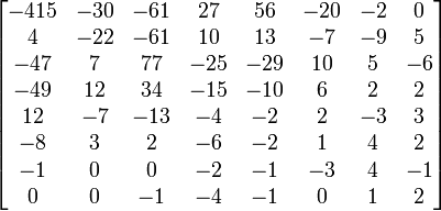
Since the DC coefficient remains mostly consistent from one block to the next, it can be compressed quite effectively with DPCM-encoding. Only the (smaller) amount of difference between each DC value needs to be stored in the final bitstream. Additionally, this DCT frequency conversion is necessary for quantization (see below).
[edit] Quantization
Quantization (of digital data) is, essentially, the process of reducing the accuracy of a signal, by dividing it into some larger step size (i.e. finding the nearest multiple, and discarding the remainder/modulus).
The frame-level quantizer is a number from 0 to 31 (although encoders will usually omit/disable some of the extreme values) which determines how much information will be removed from a given frame. The frame-level quantizer is either dynamically selected by the encoder to maintain a certain user-specified bitrate, or (much less commonly) directly specified by the user.
Contrary to popular belief, a fixed frame-level quantizer (set by the user) does not deliver a constant level of quality. Instead, it is an arbitrary metric that will provide a somewhat varying level of quality, depending on the contents of each frame. Given two files of identical sizes, the one encoded at an average bitrate should look better than the one encoded with a fixed quantizer (variable bitrate). Constant quantizer encoding can be used, however, to accurately determine the minimum and maximum bitrates possible for encoding a given video.
A quantization matrix is a string of 64-numbers (0-255) which tells the encoder how relatively important or unimportant each piece of visual information is. Each number in the matrix corresponds to a certain frequency component of the video image.
An example quantization matrix:
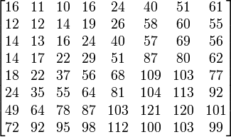
Quantization is performed by taking each of the 64 frequency values of the DCT block, dividing them by the frame-level quantizer, then dividing them by their corresponding values in the quantization matrix. Finally, the result is rounded down. This significantly reduces, or completely eliminates, the information in some frequency components of the picture. Typically, high frequency information is less visually important, and so high frequencies are much more strongly quantized (drastically reduced). MPEG-1 actually uses two separate quantization matrices, one for intra-blocks (I-blocks) and one for inter-block (P- and B- blocks) so quantization of different block types can be done independently, and so, more effectively.[2]
This quantization process usually reduces a significant number of the AC coefficients to zero, (known as sparse data) which can then be more efficiently compressed by entropy coding (lossless compression) in the next step.
An example quantized DCT block:
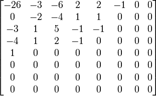
Quantization eliminates a large amount of data, and is the main lossy processing step in MPEG-1 video encoding. This is also the primary source of most MPEG-1 video compression artifacts, like blockiness, color banding, noise, ringing, discoloration, et al. This happens when video is encoded with an insufficient bitrate, and the encoder is therefore forced to use high frame-level quantizers (strong quantization) through much of the video.
[edit] Entropy Coding
Several steps in the encoding of MPEG-1 video are lossless, meaning they will be reversed upon decoding, to produce exactly the same (original) values. Since these lossless data compression steps don't add noise into, or otherwise change the contents (unlike quantization), it is sometimes referred to as noiseless coding.[15] Since lossless compression aims to remove as much redundancy as possible, it is known as entropy coding in the field of information theory.
The DC coefficients and motion vectors are DPCM-encoded.
Run-length encoding (RLE) is a very simple method of compressing repetition. A sequential string of characters, no matter how long, can be replaced with a few bytes, noting the value that repeats, and how many times. For example, if someone were to say "five nines", you would know they mean the number: 99999.
RLE is particularly effective after quantization, as a significant number of the AC coefficients are now zero (called sparse data), and can be represented with just a couple bytes. This is stored in a special 2-dimensional Huffman table that codes the run-length and the run-ending character.
Huffman Coding is a very popular method of entropy coding, used in MPEG-1 video to reduce the data size. The data is analyzed to find strings that repeat often. Those strings are then put into a special (Huffman) table, with the most frequently repeating data assigned the shortest code. This keeps the data as small as possible with this form of compression.[15] Once the table is constructed, those strings in the data are replaced with their (much smaller) codes, which reference the appropriate entry in the table. The decoder simply reverses this process to produce the original data.
This is the final step in the video encoding process, so the result of Huffman coding is known as the MPEG-1 video "bitstream."
[edit] Audio
Part 3 of the MPEG-1 standard covers audio and is defined in ISO/IEC-11172-3.
MPEG-1 Audio utilizes psychoacoustics to significantly reduce the data rate required by an audio stream. It reduces or completely discards certain parts of the audio that the human ear can't hear, either because they are in frequencies where the ear has limited sensitivity, or are masked by other (typically louder) sounds.[25]
Channel Encoding:
- Mono
- Joint Stereo (intensity encoded)
- Stereo
- Dual (two uncorrelated mono channels)
- Sampling rates: 32000, 44100, and 48000 Hz
- Bitrates: 32, 48, 56, 64, 80, 96, 112, 128, 160, 192, 224, 256, 320 and 384 kbit/s
MPEG-1 Audio is divided into 3 layers. Each progressive layer is more computationally complex, and generally more efficient (at lower bitrates) than the previous.[5] The layers are also backwards compatible, so a Layer II decoder can also play Layer I audio, but NOT Layer III audio.[25]
[edit] Layer I
MPEG-1 Layer I is nothing more than a simplified version of Layer II.[6] Layer I uses a smaller 384-sample frame size for very low-delay, and finer resolution.[11] This is advantageous for applications like teleconferencing, studio editing, etc. It has lower complexity than Layer II to facilitate real-time encoding on the hardware available circa 1990.[15]
Layer I saw limited adoption in its time, and most notably was used on Philips' defunct Digital Compact Cassette at a bitrate of 384 kbit/s.[1] With the substantial performance improvements in digital processing since its introduction, Layer I quickly became unnecessary and obsolete.
Layer I audio files typically use the extension .mp1 or sometimes .m1a
[edit] Layer II
MPEG-1 Layer II (MP2—often incorrectly called MUSICAM)[25] is a lossy audio format designed to provide high quality at about 192 kbit/s for stereo sound. Decoding MP2 audio is computationally simple, relative to MP3, AAC, etc.
[edit] History/MUSICAM
MPEG-1 Layer II was derived from the MUSICAM (Masking pattern adapted Universal Subband Integrated Coding And Multiplexing) audio codec, developed by Centre commun d'études de télévision et télécommunications (CCETT), Philips, and Institut für Rundfunktechnik (IRT)[26] [6] [5] as part of the EUREKA 147 pan-European inter-governmental research and development initiative for the development of digital audio broadcasting.
Most key features of MPEG-1 Audio were directly inherited from MUSICAM, including the filter bank, time-domain processing, audio frame sizes, etc. However, improvements were made, and the actual MUSICAM algorithm was not used in the final MPEG-1 Layer II audio standard. The widespread usage of the term MUSICAM to refer to Layer II is entirely incorrect and discouraged for both technical and legal reasons.[25]
[edit] Technical Details
Layer II/MP2 is a time-domain encoder. It uses a low-delay 32 sub-band polyphased filter bank for time-frequency mapping; having overlapping ranges (i.e. polyphased) to prevent aliasing.[27] The psychoacoustic model is based on the principles of auditory masking, simultaneous masking effects, and the absolute threshold of hearing (ATH). The size of a Layer II frame is fixed at 1152-samples (coefficients).
Time domain refers to how analysis and quantization is performed: on short, discrete samples/chunks of the audio waveform. This offers low-delay as only a small number of samples are analyzed before encoding, as opposed to frequency domain encoding (like MP3) which must analyze many times more samples before it can decide how to transform and output encoded audio. This also offers higher performance on complex, random and transient impulses (such as percussive instruments, and applause), offering avoidance of artifacts like pre-echo.
The 32 sub-band filter bank returns 32 amplitude coefficients, one for each equal-sized frequency band/segment of the audio, which is about 700 Hz wide (depending on the audio's sampling frequency). The encoder then utilizes the psychoacoustic model to determine which sub-bands contain audio information that is less important, and so, where quantization will be in-audible, or at least much less noticeable.[15]
The psychoacoustic model is applied using a 1024-point Fast Fourier Transform (FFT). Of the 1152 samples per frame, 64 samples at the top and bottom of the frequency range are ignored for this analysis. They are presumably not significant enough to change the result. The psychoacoustic model uses an empirically determined masking model to decide which sub-bands contribute more to the masking threshold, and how much quantization noise each can contain without being perceived. Any sounds below the absolute threshold of hearing (ATH) are completely discarded. The available bits are then assigned to each sub-band accordingly.[25] [27]
Typically, sub-bands are less important if they contain quieter sounds (smaller coefficient) than a neighboring (i.e. similar frequency) sub-band with louder sounds (larger coefficient). Also, "noise" components typically have a more significant masking effect than "tonal" components.[26]
Less significant sub-bands are reduced in accuracy by quantization. This basically involves compressing the frequency range (amplitude of the coefficient), i.e. raising the noise floor. Then computing an amplification factor, for the decoder to use to re-expand each sub-band to the proper frequency range.[28] [29]
Layer II can also optionally use intensity stereo coding, a form of joint stereo. This means that the frequencies above 6 kHz of both channels are combined/down-mixed into one single (mono) channel, but the "side channel" information on the relative intensity (volume, amplitude) of each channel is preserved and encoded into the bitstream separately. On playback, the single channel is played through left and right speakers, with the intensity information applied to each channel to give the illusion of stereo sound.[26] [15] This perceptual trick is known as stereo irrelevancy. This can allow further reduction of the audio bitrate without much perceivable loss of fidelity, but is generally not used with higher bitrates as it does not provide very high quality (transparent) audio.[15] [27] [30]
[edit] Quality
Subjective audio testing by experts, in the most critical conditions ever implemented (defined by ITU-R BS.1116-1), has shown MP2 to offer transparent audio compression at 256 kbit/s for 16-bit 44.1 kHz CD audio using the earliest reference implementation (more recent encoders should presumably perform even better).[31] [1] [27] [26] That (approximately) 6:1 compression ratio for CD audio is particularly impressive because it is quite close to the estimated upper limit of perceptual entropy, at just over 8:1 (approximately 176kbit/s for 44.1kHz/CD-quality stereo).[32] [33] [34] Achieving much higher compression is simply not possible without discarding some perceptible information.
Despite some 20 years of progress in the field of digital audio coding, MP2 remains the preeminent lossy audio coding standard due to its especially high audio coding performances on highly critical audio material such as castanet, symphonic orchestra, male and female voices and particularly complex and high energy transients (impulses) like percussive sounds: triangle, glockenspiel and audience applause... quite the opposite of MP3.[11] More recent testing has shown that MPEG Multichannel (based on MP2), despite being compromised by an inferior matrixed mode (for the sake of backwards compatibility)[1] [27] rates just slightly lower than much more recent audio codecs, such as Dolby Digital (AC-3) and Advanced Audio Coding (AAC) (mostly within the margin of error—and substantially superior in some cases, such as audience applause).[35] [36] This is one reason that MP2 audio continues to be used extensively.
The MPEG-2 AAC Stereo Verification Tests reached a vastly different conclusion, however, showing AAC to provide superior performance to MP2 at half the bitrate.[37] This test can be considered suspect for several reasons, however. A sample of audience applause is notably absent from this test, despite being a common staple—used across nearly all similar tests, and a characteristic strength of MPEG-1 Layer II audio. Numerous tests, performed both earlier and later, reached conclusions directly contrary to this test. Additionally, the test concludes that AAC can "provide 'indistinguishable quality'" (transparency) at 128kbit/s, a factor of 12:1 compression. This feat of audio compression vastly exceeds the upper limit of perceptual entropy, which is not theoretically possible.
Layer II audio files typically use the extension .mp2 or sometimes .m2a
[edit] Layer III/MP3
MPEG-1 Layer III (MP3) is a lossy audio format designed to provide acceptable quality at about 64 kbit/s for monaural audio over single-channel (BRI) ISDN links, and 128 kbit/s for stereo sound.
[edit] History/ASPEC
Layer III/MP3 was derived from the Adaptive Spectral Perceptual Entropy Coding (ASPEC) codec developed by the Fraunhofer Society as part of the EUREKA 147 pan-European inter-governmental research and development initiative for the development of digital audio broadcasting. ASPEC was adapted to fit in with the Layer II/MUSICAM model (frame size, filter bank, FFT, etc.), to become Layer III.[6]
ASPEC was itself based on Multiple adaptive Spectral audio Coding (MSC) by E.F. Schroeder at Thomson Consumer Electronics, Optimum Coding in the Frequency domain (OCF) the doctoral thesis by Karlheinz Brandenburg at the University of Erlangen-Nuremberg, Perceptual Transform Coding (PXFM) by J.D. Johnston at AT&T Bell Labs, and Transform coding of audio signals by Y. Mahieux and J. Petit at Centre National d'Etudes des Telecommunications (CNET).[34] [38]
[edit] Technical Details
MP3 is a frequency-domain audio transform encoder. Even though it utilizes some of the lower layer functions, MP3 is quite different from Layer II/MP2.
MP3 works on 1152 samples like Layer II, but needs to take multiple frames for analysis before frequency-domain (MDCT) processing and quantization can be effective. It outputs a variable number of samples, using a bit buffer to enable this variable bitrate (VBR) encoding while maintaining 1152 sample size output frames. This causes a significantly longer delay before output, which has caused MP3 to be considered unsuitable for studio applications where editing or other processing needs to take place.[27]
MP3 does not benefit from the 32 sub-band polyphased filter bank, instead just using an 18-point MDCT transformation on each output to split the data into 576 frequency components, and processing it in the frequency domain.[26] This extra granularity allows MP3 to have a much finer psychoacoustic model, and more carefully apply appropriate quantization to each band, providing much better low-bitrate performance.
Frequency-domain processing imposes some limitations as well, causing a factor of 12 or 36 × worse temporal resolution than Layer II. This causes quantization artifacts, due to transient sounds like percussive events and other high-frequency events that spread over a larger window. This results in audible smearing and pre-echo.[27] MP3 uses pre-echo detection routines, and VBR encoding, which allows it to temporarily increase the bitrate during difficult passages, in an attempt to reduce this effect. It is also able to switch between the normal 36 sample quantization window, and instead using 3× short 12 sample windows instead, to reduce the temporal (time) length of quantization artifacts.[27] And yet in choosing a fairly small window size to make MP3's temporal response adequate enough to avoid the most serious artifacts, MP3 becomes much less efficient in frequency domain compression of stationary, tonal components.
Being forced to use a hybrid time domain (filter bank)/frequency domain (MDCT) model to fit in with Layer II simply wastes processing time and compromises quality by introducing aliasing artifacts. MP3 has an aliasing cancellation stage specifically to mask this problem, but which instead produces frequency domain energy which must be encoded in the audio. This is pushed to the top of the frequency range, where most people have limited hearing, in hopes the distortion it causes will be less audible.
Layer II's 1024 point FFT doesn't entirely cover all samples, and would omit several entire MP3 sub-bands, where quantization factors must be determined. MP3 instead uses two passes of FFT analysis for spectral estimation, to calculate the global and individual masking thresholds. This allows it to cover all 1152 samples. Of the two, it utilizes the global masking threshold level from the more critical pass, with the most difficult audio.
In addition to Layer II's intensity encoded joint stereo, MP3 can use middle/side (mid/side, m/s, MS, matrixed) joint stereo. With mid/side stereo, certain frequency ranges of both channels are merged into a single (middle, mid, L+R) mono channel, while the sound difference between the left and right channels is stored as a separate (side, L-R) channel. Unlike intensity stereo, this process does not discard any audio information. When combined with quantization, however, it can exaggerate artifacts.
If the difference between the left and right channels is small, the side channel will be small, which will offer as much as a 50% bitrate savings, and associated quality improvement. If the difference between left and right is large, standard (discrete, left/right) stereo encoding may be preferred, as mid/side joint stereo will not provide any benefits. An MP3 encoder can switch between m/s stereo and full stereo on a frame-by-frame basis.[26] [39] [30]
Unlike Layers I/II, MP3 uses variable-length Huffman coding (after perceptual) to further reduce the bitrate, without any further quality loss.[25] [27]
[edit] Quality
These technical limitations inherently prevent MP3 from providing critically transparent quality at any bitrate. This makes Layer II sound quality actually superior to MP3 audio, when it is used at a high enough bitrate to avoid noticeable artifacts. The term "transparent" often gets misused, however. The quality of MP3 (and other codecs) is sometimes called "transparent," even at impossibly low bitrates, when what is really meant is "good quality on average/non-critical material," or perhaps "exhibiting only non-annoying artifacts."
MP3's more fine-grained and selective quantization does prove notably superior to Layer II/MP2 at lower-bitrates, however. It is able to provide nearly equivalent audio quality to Layer II, at a 15% lower bitrate (approximately).[36] [37] 128 kbit/s is considered the "sweet spot" for MP3; meaning it provides generally-acceptable quality stereo sound on most music, and there are diminishing quality improvements from increasing the bitrate further. MP3 is also regarded as exhibiting artifacts that are less-annoying than Layer II, when both are used at bitrates that are too low to possibly provide faithful reproduction.
Layer III audio files use the extension .mp3
[edit] MPEG-2 Audio Extensions
The MPEG-2 standard includes several extensions to MPEG-1 Audio.[27] MPEG-2 Audio is defined in ISO/IEC-13818-3
- MPEG Multichannel ISO/IEC 14496-3. Backward compatible 5.1-channel surround sound.[10]
- Sampling rates: 16000, 22050, and 24000 Hz
- Bitrates: 8, 16, 24, 32, 40, 48, 56, 64, 80, 96, 112, 128, 144, and 160 kbit/s
These sampling rates are exactly half that of those originally defined for MPEG-1 Audio. They were introduced to maintain higher quality sound when encoding audio at lower-bitrates.[10] These additional (lower) bitrates were introduced because tests showed that MPEG-1 Audio could provide higher quality than any existing (circa 1994) very low bitrate (i.e. speech) audio codecs.[40]
[edit] Conformance Testing
Part 4 of the MPEG-1 standard covers conformance testing, and is defined in ISO/IEC-11172-4.
Conformance: Procedures for testing conformance.
Provides two sets of guidelines and reference bitstreams for testing the conformance of MPEG-1 audio and video decoders, as well as the bitstreams produced by an encoder.[5] [8]
[edit] Reference Software
Part 5 of the MPEG-1 standard includes reference software, and is defined in ISO/IEC-11172-5.
Simulation: Reference software.
C language reference code for encoding and decoding of audio and video, as well as multiplexing and demultiplexing.[5] [8]
This includes the ISO Dist10 audio encoder code, which LAME and TooLAME were based upon.
[edit] References
- ↑ 1.0 1.1 1.2 1.3 1.4 1.5 Adler, Mark; Popp, Harald; Hjerde, Morten (November 9, 1996), MPEG-FAQ: multimedia compression [1/9], faqs.org, http://www.faqs.org/faqs/mpeg-faq/part1/, retrieved 2008-04-09
- ↑ 2.0 2.1 2.2 2.3 2.4 2.5 2.6 2.7 Le Gall, Didier (April, 1991), MPEG: a video compression standard for multimedia applications, Communications of the ACM, http://www.cis.temple.edu/~vasilis/Courses/CIS750/Papers/mpeg_6.pdf, retrieved 2008-04-09
- ↑ Chiariglione, Leonardo (October 21, 1989), Kurihama 89 press release, ISO/IEC, http://www.chiariglione.org/mpeg/meetings/kurihama89/kurihama_press.htm, retrieved 2008-04-09
- ↑ 4.0 4.1 Chiariglione, Leonardo (March, 2001), Open source in MPEG, Linux Journal, http://www.chiariglione.org/leonardo/publications/linux/linux00.htm, retrieved 2008-04-09
- ↑ 5.00 5.01 5.02 5.03 5.04 5.05 5.06 5.07 5.08 5.09 5.10 5.11 Fogg, Chad (April 2, 1996), MPEG-2 FAQ, University of California, Berkeley, http://bmrc.berkeley.edu/research/mpeg/faq/mpeg2-v38/faq_v38.html, retrieved 2008-04-09
- ↑ 6.0 6.1 6.2 6.3 Chiariglione, Leonardo; Le Gall, Didier; Musmann, Hans-Georg; Simon, Allen (September, 1990), Press Release - Status report of ISO MPEG, ISO/IEC, http://www.chiariglione.org/mpeg/meetings/santa_clara90/santa_clara_press.htm, retrieved 2008-04-09
- ↑ Meetings, ISO/IEC, http://www.chiariglione.org/mpeg/meetings.htm, retrieved 2008-04-09
- ↑ 8.0 8.1 8.2 Achievements, ISO/IEC, http://www.chiariglione.org/mpeg/achievements.htm, retrieved 2008-04-03
- ↑ Chiariglione, Leonardo (November 6, 1992), MPEG Press Release, London, 6 November 1992, ISO/IEC, http://www.chiariglione.org/mpeg/meetings/london/london_press.htm, retrieved 2008-04-09
- ↑ 10.0 10.1 10.2 Wallace, Greg (April 2, 1993), Press Release, ISO/IEC, http://www.chiariglione.org/mpeg/meetings/sydney93/sydney_press.htm, retrieved 2008-04-09
- ↑ 11.0 11.1 11.2 11.3 Popp, Harald; Hjerde, Morten (November 9, 1996), MPEG-FAQ: multimedia compression [2/9], faqs.org, http://www.faqs.org/faqs/mpeg-faq/part2/, retrieved 2008-04-10
- ↑ Ozer, Jan (October 12, 2001), Choosing the Optimal Video Resolution: The MPEG-2 Player Market, extremetech.com, http://www.extremetech.com/article2/0,1697,1153916,00.asp, retrieved 2008-04-09
- ↑ Comparison between MPEG 1 & 2, snazzizone.com, http://www.snazzizone.com/TP09.html, retrieved 2008-04-09
- ↑ MPEG 1 And 2 Compared, Pure Motion Ltd., 2003, http://213.130.34.82/resources/technical/mpegcompared/index.htm, retrieved 2008-04-09
- ↑ 15.0 15.1 15.2 15.3 15.4 15.5 15.6 Grill, B.; Quackenbush, S. (October, 2005), MPEG-1 Audio, ISO/IEC, http://www.chiariglione.org/mpeg/technologies/mp01-aud/index.htm, retrieved 2008-04-03
- ↑ Chiariglione, Leonardo, MPEG-1 Systems, ISO/IEC, http://www.chiariglione.org/mpeg/faq/mp1-sys/mp1-sys.htm, retrieved 2008-04-09
- ↑ 17.0 17.1 Pack Header, http://dvd.sourceforge.net/dvdinfo/packhdr.html, retrieved 2008-04-07
- ↑ Fimoff, Mark; Bretl, Wayne E. (December 1, 1999), MPEG2 Tutorial, http://www.bretl.com/mpeghtml/STC.HTM, retrieved 2008-04-09
- ↑ Fimoff, Mark; Bretl, Wayne E. (December 1, 1999), MPEG2 Tutorial, http://www.bretl.com/mpeghtml/PTS.HTM, retrieved 2008-04-09
- ↑ Fimoff, Mark; Bretl, Wayne E. (December 1, 1999), MPEG2 Tutorial, http://www.bretl.com/mpeghtml/DTS.HTM, retrieved 2008-04-09
- ↑ Fimoff, Mark; Bretl, Wayne E. (December 1, 1999), MPEG2 Tutorial, http://www.bretl.com/mpeghtml/VBV.HTM, retrieved 2008-04-09
- ↑ Acharya, Soam; Smith, Brian (1998), Compressed Domain Transcoding of MPEG, Cornell University, IEEE Computer Society, ICMCS, pp. 3, http://citeseer.ist.psu.edu/acharya98compressed.html, retrieved 2008-04-09 - (Requires clever reading: says quantization matrices differ, but those are just defaults, and selectable)
- ↑ 23.0 23.1 23.2 Wee, Susie J.; Vasudev, Bhaskaran; Liu, Sam (March 13, 1997), Transcoding MPEG Video Streams in the Compressed Domain, HP, http://web.archive.org/web/20070817191927/http://www.hpl.hp.com/personal/Susie_Wee/PAPERS/hpidc97/hpidc97.html, retrieved 2008-04-01
- ↑ being centered around 0, by subtracting the values by half the number of possible values (i.e. 128)
- ↑ 25.0 25.1 25.2 25.3 25.4 25.5 Thom, D.; Purnhagen, H. (October, 1998), MPEG Audio FAQ Version 9, ISO/IEC, http://www.chiariglione.org/MPEG/faq/mp1-aud/mp1-aud.htm, retrieved 2008-04-09
- ↑ 26.0 26.1 26.2 26.3 26.4 26.5 Church, Steve, Perceptual Coding and MPEG Compression, NAB Engineering Handbook, Telos Systems, http://www.telos-systems.com/techtalk/mpeg/default.htm, retrieved 2008-04-09
- ↑ 27.0 27.1 27.2 27.3 27.4 27.5 27.6 27.7 27.8 27.9 Pan, Davis (Summer, 1995), A Tutorial on MPEG/Audio Compression, IEEE Multimedia Journal, pp. 8, http://www.cs.columbia.edu/~coms6181/slides/6R/mpegaud.pdf, retrieved 2008-04-09
- ↑ Smith, Brian (1996), A Survey of Compressed Domain Processing Techniques, Cornell University, pp. 7, http://citeseer.ist.psu.edu/257196.html, retrieved 2008-04-09
- ↑ Cheng, Mike, Psychoacoustic Models in TooLAME/TwoLAME, twolame.org, http://www.twolame.org/doc/psycho.html, retrieved 2008-04-09
- ↑ 30.0 30.1 Herre, Jurgen (October 05, 2004), From Joint Stereo to Spatial Audio Coding, Conference on Digital Audio Effects, pp. 2, http://dafx04.na.infn.it/WebProc/Proc/P_157.pdf, retrieved 2008-04-17
- ↑ Grewin, Christer & Rydén, Thomas (September 1991) Subjective Assessments on Low Bit-Rate Audio Codecs, Proceedings of the 10th International AES Conference: Images of Audio, pp 91 - 102, London
- ↑ J.D. Johnston (April, 1988) Estimation of Perceptual Entropy Using Noise Masking Criteria, in International Conference on Acoustics, Speech, and Signal Processing, ICASSP-88, vol.5, pp. 2524-2527
- ↑ J.D. Johnston (February, 1988) Transform Coding of Audio Signals Using Perceptual Noise Criteria, IEEE Journal Select Areas in Communications, vol. 6, no. 2, pp. 314-323
- ↑ 34.0 34.1 Painter, Ted; Spanias, Andreas (April, 2000), Perceptual Coding of Digital Audio (PROCEEDINGS OF THE IEEE, VOL. 88, NO. 4), Proceedings of the IEEE, http://www.eas.asu.edu/~spanias/audiopaper1.pdf, retrieved 2008-04-01
- ↑ Wüstenhagen, Ulf; Feiten, Bernhard & Hoeg, Wolfgang (September, 1998) Subjective Listening Test of Multi-channel Audio Codecs, AES 105th Convention Paper 4813, San Francisco
- ↑ 36.0 36.1 B/MAE Project Group (September, 2007), EBU evaluations of multichannel audio codecs, European Broadcasting Union, http://www.ebu.ch/CMSimages/en/tec_doc_t3324-2007_tcm6-53801.pdf, retrieved 2008-04-09
- ↑ 37.0 37.1 Meares, David; Watanabe, Kaoru; Scheirer, Eric (February, 1998), Report on the MPEG-2 AAC Stereo Verification Tests, ISO/IEC, pp. 18, http://sound.media.mit.edu/mpeg4/audio/public/w2006.pdf, retrieved 2008-04-16
- ↑ Brandenburg, Karlheinz; Herre, Jürgen; Johnston, James D.; Mahieux, Yannick & Schroeder, Ernst F. (February 1991) Aspec-Adaptive Spectral Entropy Coding of High Quality Music Signals AES Convention 90, No. 3011
- ↑ Amorim, Roberto (September 19, 2006), GPSYCHO - Mid/Side Stereo, LAME, http://lame.sourceforge.net/ms_stereo.php, retrieved 2008-04-17
- ↑ Chiariglione, Leonardo (November 11, 1994), Press Release, ISO/IEC, http://www.chiariglione.org/mpeg/meetings/singapore94/singapore_press.htm, retrieved 2008-04-09
| |
Some content on this page may previously have appeared on Citizendium. |